- #Pinagem cabo rs232 serial#
- #Pinagem cabo rs232 driver#
- #Pinagem cabo rs232 full#
- #Pinagem cabo rs232 software#
#Pinagem cabo rs232 software#
Many of the 22 signal lines in the EIA232 standard pertain to connections where the DCE device is a modem, and then are used only when the software protocol employs them. The most commonly used signals are shown in bold.
#Pinagem cabo rs232 full#
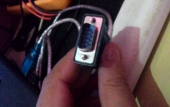
This shows the full EIA232 signal definition for the DCE device (usually the modem). Here is the full EIA232 signal definition for the DTE device (usually the PC). DCE devices are sometimes called "Data Communications Equipment" instead of Data Circuit-terminating Equipment. This drawing shows the orientation and connector types for DTE and DCE devices:ĮIA232 communication function and connector types for a personal computer and modem. If all devices exactly followed this standard, all cables would be identical, and there would be no chance that an incorrectly wired cable could be used. The cable linking DTE and DCE devices is a parallel straight-through cable with no cross-overs or self-connects in the connector hoods. Equipment at the near end of the connection (the telephone line interface) is named the DCE device (Data Circuit-terminating Equipment, usually a modem), has a female DB25 connector, and utilizes the same 22 available pins for signals and ground. If the full EIA232 standard is implemented as defined, the equipment at the far end of the connection is named the DTE device (Data Terminal Equipment, usually a computer or terminal), has a male DB25 connector, and utilizes 22 of the 25 available pins for signals or ground.
#Pinagem cabo rs232 serial#
Go to DCE Pinout (looking into the modem's serial connector) Go to DTE Pinout (looking into the computer's serial connector) In any case, if the serial interface between two devices is not operating correctly, disconnect the cable joining this equipment until the problem is isolated.
#Pinagem cabo rs232 driver#
Most of the difficulties you will encounter in EIA232 interfacing include at least one of the following:ġ - The absence or misconnection of flow control (handshaking) signals, resulting in buffer overflow or communications lock-up.Ģ - Incorrect communications function (DTE versus DCE) for the cable in use, resulting in the reversal of the Transmit and Receive data lines as well as one or more handshaking lines.ģ - Incorrect connector gender or pin configuration, preventing cable connectors from mating properly.įortunately, EIA232 driver circuitry is highly tolerant of misconnections, and will usually survive a drive signal being connected to ground, or two drive signals connected to each other. Because no single "simplified" standard was agreed upon, however, many slightly different protocols and cables were created that obligingly mate with any EIA232 connector, but are incompatible with each other. Today, virtually all contemporary serial interfaces are EIA232-like in their signal voltages, protocols, and connectors, whether or not a modem is involved. Besides changing the name from RS232 to EIA232, some signal lines were renamed and various new ones were defined, including a shield conductor.ĭuring this 40-year-long, rapidly evolving period in electronics, manufacturers adopted simplified versions of this interface for applications that were impossible to envision in the 1960s. Over the 40+ years since this standard was developed, the Electronic Industries Association published three modifications, the most recent being the EIA232F standard introduced in 1997. It specified signal voltages, signal timing, signal function, a protocol for information exchange, and mechanical connectors.

From these ideas, the RS232 standard was born. It was thought that a standard was needed first to ensure reliable communication, and second to enable the interconnection of equipment produced by different manufacturers, thereby fostering the benefits of mass production and competition. While simple in concept, the many opportunities for data error that occur when transmitting data through an analog channel require a relatively complex design. These devices were linked by telephone voice lines, and consequently required a modem at each end for signal translation.

At that time, data communications was thought to mean digital data exchange between a centrally located mainframe computer and a remote computer terminal, or possibly between two terminals without a computer involved. In the early 1960s, a standards committee, today known as the Electronic Industries Association, developed a common interface standard for data communications equipment. Likely Problems when Using an EIA232 Interface (renamed the "EIA232 Standard" in the early 1990's)Ĭopyright © 1993-2015 by CAMI Research Inc., Acton, Massachusetts

A Tutorial with Signal Names and Definitions


 0 kommentar(er)
